
Vol. 4 N° 1, enero-junio 2023, pag. 68-81
ISSN 2618-5520 on line
DOI - https://doi.org/10.36995/j.masingenio.2022.12.12.006
EXPERIMENTAL STUDY OF A CENTRIFUGAL PUMP OPERATING AS A HYDRAULIC TURBINE
Orlando Aníbal Audisioa, https://orcid.org/0000-0001-9960-7600,
(orlando.audisio@fain.uncoma.edu.ar)
Mariano Nicolás
Rossia, (rossi.mariano.nicolas@gmail.com)
Paul José Alonsoa,
(pauljosealonso@gmail.com)
a University Nac. del Comahue (UNCo), School of Mechanical Engineering, Code Investigation Project: 04/I229 U.N.Co. –U.Na.M
Abstract
An experimental investigation of centrifugal pump has been carried out to study its characteristics in pump and turbine mode operation (PAT). The correlation between pump and PAT performance is a major problem. Several methods have been developed to predict the best efficiency of pumps running as turbines but their results are not in good coincidence with experimental data for all pumps. Fluid dynamic behavior of PAT changes appreciably, in to its localized and distributed hydraulic losses, velocity profiles and pressures at homologous points. It is not possible to infer the behavior of a PAT using similarity parameters from pump mode performance; very large errors are made.
This paper presents the experimental parameters of operating of a PAT with specific number low. In order to determine the pump’s characteristic as turbine, we used a closed circuit experimental setup in which the admission pressure head was realized with another pump and, the correlation between the diameter of the PAT and the specific number for 3 different ranges of flow is determined. This is based on an experimental data base on a centrifugal pump of specific number 17,80 [RPM, m3/s, m] in both rotation modes and for a speed range of rotation between 250 and 2500 RPM. All required parameters were measured to achieve complete characteristic curves of the reverse pump
The functional characterization show curves of the hydraulic machine in the turbine mode with variation of operating parameters such as rotation speeds, heights, and flow rates. With the results obtained, the comparatives are made that allows observing the influence of the same on the performance of the PATs.
Curves are obtained that allow inferring the behavior in turbine mode from pump mode parameters. Values obtained from the derived correlations show good match with experimental results. These correlations would be very helpful for the performance prediction of pump working as turbine.
Key Word: Energy converter - Turbines - Pumps – PAT – Hydraulic Energy
List of Symbols
Φ Characteristic Diameter [m] HN Net Specific Energy [m]
ns Specific Speed [RPM, kW, m] n Speed [RPM]
Q Nominal Flow [m3/s] PH Hydraulic Power [kW]
Pe Shaft Power [kW] η Performance [%]
Ψ Head Coefficient [g.HN/(n.Φ)2] Φ Flow Coefficient [Q/(n.Φ3)]
λ Length scale ![]() θ Time scale
θ Time scale ![]()
α Kinematic
pressure scale ![]()
k Kinematic Viscosity Scale ![]()
Introduction
For several decades, reverse-running pumps have found various applications as turbines in industrial environments, and more recently they have been successfully used in stand-alone and grid-linked hydropower, especially in developed countries. On account of the much larger size of their market, pumps used as turbines (PATs), and their spares, are cheaper and more promptly available than conventional turbines, and their maintenance is easier due to the broad availability of spares and know-how. However, there are still many areas of uncertainty that have hampered their dissemination, particularly in the context of developing countries.
The principal difference between a PAT and a conventional turbine is the former's lack of a flow control device. This is at the same time an advantage-it makes it cheaper, and a disadvantage: it makes it less versatile. The disadvantage has been reduced by the advent of electronic load controllers, that keep the generator torque constant by switching in ballast loads whenever electrical demand drops. Due to their fixed geometry, PATs also require constancy in their drive conditions. Seasonal flow variations have been met either by simply designing the system for the minimum annual flow or by operating several machines in parallel.
The dissemination of PATs has been hampered by a lack of information. Especially in developing countries, even the pump manufacturers ignore the turbine-mode performance of their pumps.
It is hoped that the contributions made here to reduce the areas of uncertainty in PAT knowledge will promote the use of this technology and hence of micro-hydro. The development of small-scale hydropower reduces the emissions of CO2. SO., and NOx and therefore slightly contributes to the control of the greenhouse effect. However, the impact of the availability of energy on rural development makes micro-hydro even more promising for the isolated rural communities of developing countries, where it is in many cases the only feasible inanimate energy source.
One of the economic alternatives in small hydro power (SHP) is to use the centrifugal pumps in reverse mode. Research on the use of pumps as turbines (PAT) began in the early 1930s and with increasing energy demand, it became more economically feasible to exploit such energy sources. However, what once was an academic exercise or a curiosity, today has gained special interest as a result of environmental, socioeconomic and technical factors of recent emergence.
Considering technical and socioeconomic aspects, it is worth noting the renewed interest in the use of small streams where the costs of hydro mechanical equipment represents a very important investment percentage of the total. In small and very small hydroelectric power plants (less than 100 kW), centrifugal pumps used as hydraulic turbines (PAT) a significant reduction of the investment of machinery of the order of 10 to one is achieved and in some very particular cases, even more is achieved.
These applications are more interesting due to the advances made in the control and regulation technology of electric machines, which allow the regulation of drives with speed, direction of rotation and torque sense, variables, both in direct current and in alternating current in their type single phase and three phases.
For the work it is important to characterize the PAT and a suitable test bench has been designed and built, composed of an open circuit equipped with two centrifugal pumps (series and parallel) that provides the pressure and flow required in the test, and an open tank which is also used for regulation. The pump under study is a free shaft and is coupled directly to the dynamometer type "Currents parasites or Foucault".
Once the calibration of all the equipment and instrumentation (tachometers, load cell, column manometers, flowmeters, etc.) has been obtained, the performance curves of the PAT have been obtained to make the analysis and comparative with the curves in the mode pump from the manufacturer's data.
Reverse Mode Operation
When a centrifugal pump operates as a turbine, flow and rotating directions are reverse. There is one passage with two opposite flows and rotating directions. The main problem and greatest challenge in the technology related to the PAT is in the selection of the most suitable pump and available in the market to satisfy a determined application like turbine. The selection has conditions of input (height), and output (flow) edges, to which are added the conditions assumed for minimum load and rotation speed.
As discussed earlier several methods have been proposed for prediction of reverse operation of centrifugal pump.
But error of more than ±20% has been obtained, when compared with experimental results [5] and any method is 100% reliable to predict accurate turbine performance. Therefore, these methods are confined to preliminary selection of pumps to be used as turbines. Also, methods to predict turbine mode performance from pump mode data have much importance because pump manufacturers provide characteristics curves for pump mode only.
However, the preliminary selection of PAT is important to obtain a rough estimation of turbine mode characteristics from pump mode characteristics. The simplest way to select a pump for a micro hydropower is prediction of turbine characteristics of the pump from its pump mode characteristics. But prediction of turbine characteristics of a pump from pump characteristics is always a big challenge because this gives an approximate turbine mode performance characteristic. Accurate prediction of turbine performance from pump data can make the preliminary selection of PAT for a particular micro hydropower site more easy and quick.
The previous PAT performance prediction methods were based on either efficiency or specific speed of pump. This parameters are most use to define hydraulic performance of a centrifugal pump. Specific speed is a non-dimensional parameter which contains head, discharge and speed of the pump. It acts as tool to compare pumps and select appropriate pump for a particular situation. Therefore, the specific speed parameter cannot be neglected to develop a more accurate method for determining the performance of a PAT. However, there is no parameter which can alone relate to all aspects of final pump design therefore considering both pump efficiency and specific speed can help to predict accurate prediction of reverse operation of centrifugal pump.
Is important to relate pump efficiency with specific speed, and there is a particular value at which maximum efficiency is obtained. In fact efficiency and specific speed relation is very useful to find approximate relative impeller shapes (axial, mixed and radial flow) and average coefficients of centrifugal pumps. In addition to this, it tells about the probable limit of economical operation of pump. The head and discharge values at BEP in turbine mode are higher than in pump mode. This increase in head and flow rate in turbine mode varies according to the specific speed [5].
The studies carried out to date [1], [2] and [3] were basically aimed at estimating the performance of the PAT in pump mode, by standardizing characteristic curves and determining HT/HB ratios and QT/QB, for the conditions of maximum performance and as a function of the specific number or speed [4].
However, the observed discrepancies between the data provided by different authors are large, which leads us to believe that there are design parameters other than the specific speed that influence the behavior in turbine mode.
One of them, the relative value of the carcass-impeller air gap, has been well studied by a research team at the University of Hannover. It is demonstrated that the clearance influences more in the normal operation than in turbine mode, causing smaller yield decreases.
Most of the studies are based on the hypothesis of the similarity between the optimum efficiency in both modes of operation and equal velocities for both modes of operation, which is not easy to sustain. From this hypothesis we determine algebraic relations that have as explanatory variable to the efficiency.
There is very little information on specific experimental aspects in which, for a given pump, the variations of the behavior in reverse mode are studied against other parameters such as height, speed of rotation, flow rates, unit parameters, etc.
Another important aspect that emerges from work and analyzed by other researchers, is linked to the fact that it has not yet been possible to find a generalized application methodology to make the selection of PAT. In our view, the lack of systematization and generalization in the selection of PAT is related to the methodology designed to determine hydraulic parameters in the turbine mode; are always aimed at considering as explanatory variables the performance and the specific number of the pump in question, both of which are inexorably linked to the conditions of similarity or affinity between model and prototype.
Analyzing and working the hydraulic similarity between model and prototype, there are fundamentally analogies of geometric, kinematic and dynamic type.
This applies to a PAT, between a rotor of a pump operating as such and operating in the reverse direction, these analogies are completely lost so that it is not reasonable to think that the same turbomachinery running in pump mode and, running in turbine mode, can to become one the model and another the prototype; in the reversal of the direction of flow and rotation the physical and geometrical considerations underlying the hydraulic similarity are completely lost.
There must be a one-to-one correspondence between two turbomachines, and this bi-univocal or point-to-point correspondence between model and prototype logically leads to line-by-line, surface-to-surface, volume-to-volume, and mass-by-line. dough. In addition, as the turbomachines have displacement or movement, there must also be correspondence in times and positions.
For this reason, the corresponding fluid particles must travel equally similar trajectories geometrically and the associated corresponding current lines must have the same qualities. These aspects are not possible to satisfy in a pump impeller turning in the reverse direction (PAT). It is therefore important to develop experimental research in order to have an important and reliable database.
From these considerations we can find a response to why, so much work of different researchers have failed to find a methodology of general application to infer the behavior of a centrifugal pump operating as a hydraulic turbine (PAT). Many of the works done have only served to explain specific cases that, in many cases, represented their own and particular needs but never came to represent expressions of widespread use; these expressions taken to other applications have shown errors ranging from 20% and up to 100% [5].
In order to support the above appraisals, we must resort to the differential equation that represents the motion of a viscous fluid (Navier-Stokes equation-NS) and further defines the motion of a fluid. In addition, the N-S equation explains both the flow behavior in the prototype and the model.
In this context, when the dimensions of the prototype are known and its flow is defined by the expression of NS, the terms of the equation that defines the behavior of the flow in the model will be obtained by multiplying by certain scale relations, each term of the equation that explains the flow behavior in the prototype.
These relationships represent the value of each parameter in the model and the value of the same parameter in the prototype. Then, by affecting each term of the starting N-S equation by the corresponding ratios we will obtain the equation that defines the flow in the model. Therefore the equation that defines the flow behavior in the model is:
|
|
For the two equations of NS to define similar physical phenomena between the movement of the fluid in model and in prototype, they must be necessarily equal or proportional. If this does not happen, then it would be different physical facts and there would be no proportionality or similarity. Then it will be verified that:
|
|
If the value of n is different from unity, the position gradient would be multiplied by ng, which is to say that the physical phenomenon would be subjected to a gravity other than that of the terrestrial, which is impossible.
In addition, when the scale of lengths is fixed, the dependence between the kinematic viscosities of the prototype and the model is determined. So if the gravity and viscosity of the fluids to be used in prototype and model must be the same, the geometric scale must be the unit.
This is the relevant thing that happens in the PAT; the same machine is operated in the reverse direction and therefore this is where it begins to not comply with the hydrodynamic similarity. It is not possible to begin to fulfill the geometric similarity, which is the starting point to generate the other conditions of hydrodynamic similarity.
Conclusions: it is not possible to think of complying with the physical precepts required by the hydraulic similarity between model and prototype for the simple reason that a pump is not similar to the pump itself but working as a hydraulic turbine rotating in reverse. In addition, this indicates that from the physical point of view, it will never be possible to pass a value in pump mode to the turbines mode using as an explanatory variable parameters of similarity: a centrifugal pump and the same PAT are not similar turbomachines.
Due to the above, and in accordance with the objectives of this paper, it is very important to have guaranteed databases and experimental type centrifugal pumps operating in turbine mode.
Experimental Procedure
The performance tests and the field of operation of the PAT were carried out in the Laboratory of Hydraulic Machines of the Faculty of Engineering of the National University of Comahue (UNCo). The test was performed for a range of flow rates. Measurements were developed by applying the rules emanating from the IEC, BSI, and DIN standards. The experimental procedure involves the measurement of 4 parameters: Height, Flow, Rotation Speed and torque in the axis of the PAT. The test rig used in the present experimental study is showed in Figure No. 01.
|
|
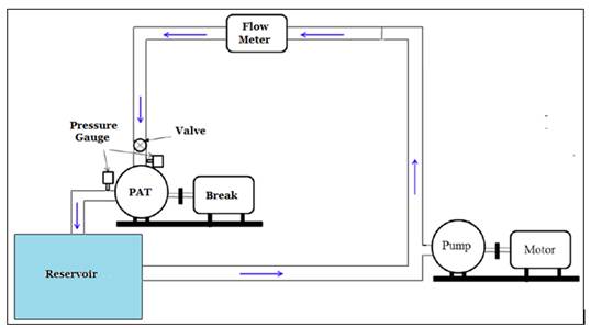
Figure Nº 01: Schematic diagram of experimental test rig (pump in pump mode).
In the test ring the head and the flow required is provided by two horizontal axis centrifugal pumps with of 18 kW (25 HP) and 1500 RPM each pumps, which take from a tank open to the atmosphere and with globe valves in the discharge of the same. By a system of valves and pipes with an arrangement for this purpose, the flow enters the pump under study, yielding energy to the same and returning to the tank through the aspiration tube of the model turbomaquina. During the test, the model is controlled by a brake to eddy currents or Foucault.-
The flow rate is measured with an electromagnetic flowmeter or with orifice plate normalized to BS and calibrated in situ. The static height is measured through a "U" pressure gauge to a mercury column and is corrected by the contribution of kinetic energy to determine the specific energy per unit mass exchanged in the test. The torque measurement is performed with a load cell and the speed of rotation with a digital tachometer, both linked to the dynamometric brake. These parameters allow us to determine the mechanical power delivered by the PAT.
The experimental parameters were obtained from the prototype shown in Photo No 01. The pump tested (green color) as turbine (PAT) and a dynametric brake type Foucault currents (blue color) are observed.
|
|
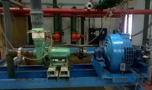
Photo Nº 01: Pumps used as Turbines in test ring.
Results and discussions
We tested industrial centrifugal pumps available in market without any modification for operating as turbines at various rotational speeds (1000 rpm, 1500 rpm, 2000 rpm and \2500 rpm). In each rotational speed the head, flow rate and power were measured. A standard radial centrifugal pump Peerlees brand C & F Type F1 820AM 2x2½x8- Peerless Pump Company Indianapolis. Nominal Flow of 150 USGPM, Nominal Total Net Height of 52 Feet, Effective Performance of 70%, Rotation Speed of 1750 RPM and Rotor Diameter of 8 inches (measured on the equipment was 203,60 mm), net discharge width of the impeller of 8,50 mm, Net Diameter Impeller of 63,60 mm and it has 8 blades. The performance curves delivered by its manufacturer are shown in Diagram Nº 01.
|
|
|
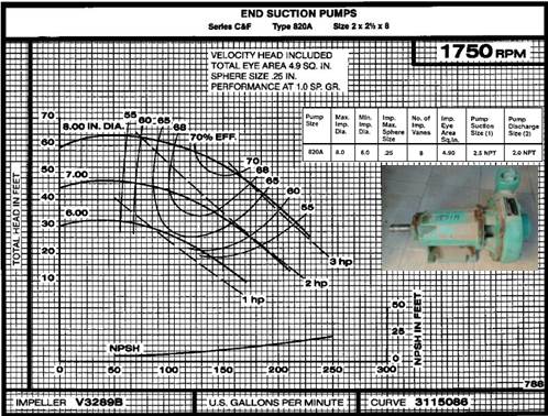
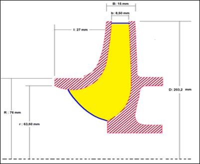
Diagram Nº 01: Performance curves Centrifugal Pumps Peerlees Pump Company
In this paper, an experimental test was presented to calculate best efficiency point and other performance curves of reverse pump. The performance directly depends on the performance of PAT. Hence, most of the researchers have studied the performance in both modes at same rotational speeds either experimentally (Derakhshan and Nourbakhsh, 2008b; Nautiyal et al., 2011) or numerically (Barrio et al., 2010; Fernandez et al., 2010). But, the BEP in turbine mode is obtained at higher head and discharge than that in the pump mode (Fernandez et al., 2004; Prasad et al., 2006; Rawal and Kshirsagar, 2007; Shukla, 2008; Barrio et al., 2010).
Consequently, the pattern of hydraulic loss distribution, flow instabilities and the radial imbalance generated in turbine mode are expected to be different compared to that in the pump mode. Also, the studies on force analysis revealed that, there exists higher axial thrust in turbine mode compared to pump mode (Morros et al., 2011). These parameters may affect the energy transformation process in turbine mode compared to that in pump mode at different rotational speeds. Hence, it is required to study the performance of PAT at different rotational speeds.
As an experimental result, the parameters Q, H, n and T were obtained, which are shown in Table 01.
Table Nº 01: Experimental Results
|
|
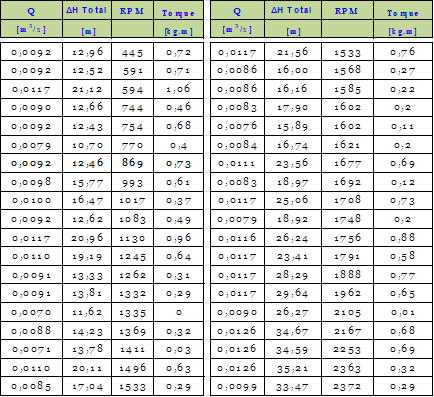
In experimental form and under the exposed procedures, operating variables have been obtained for a range of rotation speed between 250 and 2500 RPM. For these velocity, the operating flow, static inlet and discharge pressure, and brake torque were identified, which together with the speed of rotation are the four fundamental operating parameters to identify the different performance curves of this PAT. Graph Nº 01 shows the variation of rotation speed as a function of the Flow Coefficient and for different high, and the variation of the height coefficient as a function of the flow Coefficient.
|
|
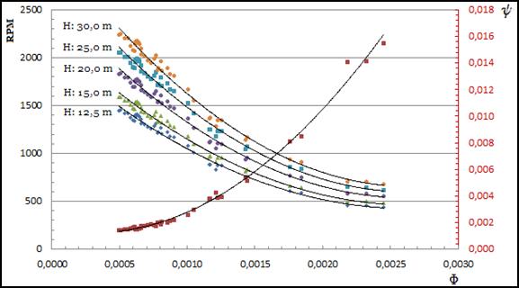
Graph Nº 01: Rotation Speed (RPM) and Height Coef. vs. Flow Coef. (PAT)
Efficiency: The overall efficiency coefficients (ηtot) of the hydraulic machine (PAT) are plotted in Graph No. 02.- In it is observed that the BEP is 47% and it is obtained for a flow coefficient of 0,00144; the calculated efficiencies in PAT include hydraulic losses, leakage flow losses, disc friction power losses and bearing power losses, and the powers is what is really obtained in the axis of the PAT [see Diagram Nº 01]. In the partial-load range of turbine operation, a steeper drop in efficiency is evident when compared to pump mode.
|
|
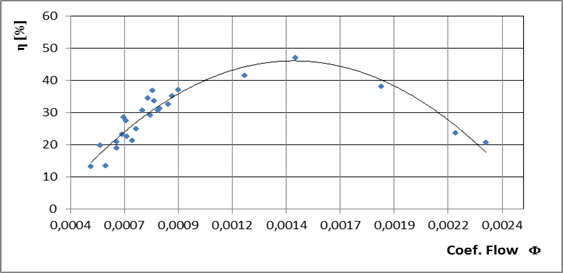
Graph Nº 02: Efficiency vs. Flow Coef. (PAT)
|
|
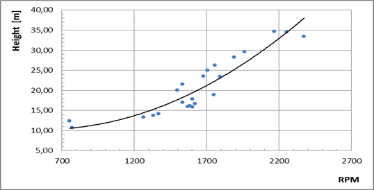
Grafico Nº 03: Net Height vs. Rotation Speed [RPM] (PAT)
|
|
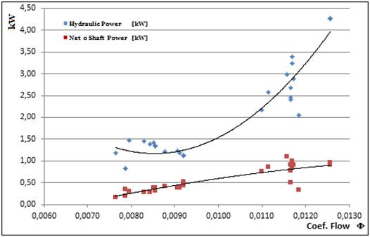
Graph Nº 04: Hydraulic Power Input and Mechanical Power Output (Shaft) vs. Flow (PAT)
With respect to geometric variables, the characteristic diameter of the rotor can be determined with the following expression:
|
|
The parameters that yielded the tests within a range of specific numbers from 12 to 19, can be seen in Graph No. 05 three very marked trends in the variation of the characteristic diameter of the PAT for nominal flows of operation.
|
|
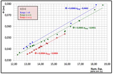
Graph Nº 05: Diameter Prototype vs. Specific Number (PAT)
|
|
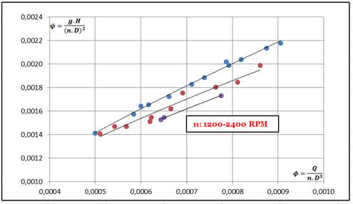
Graph Nº 06: Head vs. Flow Coefficient for different n (PAT)
Results and Conclusions
According to manufacturer's information, the pump has an H vs. Q with high stability. With respect to this pump but in turbine mode, it is observed in the graph Nº 01, that the experimental values give a curve with tendency equal to those that fix the theoretical and experimental precepts developed by other researchers.
The graph Nº 01 shows the rotation speed of the PAT. the variation of the flow and for constant jumps. This set of curves do not go through the origin of coordinates, which shows that it is necessary to have a flow and a minimum height at the entrance, so that the PAT can begin to rotate (void flow).
Graph No. 02 shows the variation of turbine performance at flow rate which reached a maximum value of 47%. It emphasizes the increase of the yield until a rate that makes maximum to this yield, later to return to decay again as we increase the flow. The curve presents a variation of parabolic type, according to the theories considerations applied to this type of turbomachinery.-
Graph No. 04 shows the variation of the input hydraulic power and the power obtained in the axis of the PAT for a variation of flow. Both powers increase as the flow also increases. Aspect that is compatible with the theoretical developments based on the application of the fundamental equation of the turbomachinery (Euler). The pump operates without problem in different rotational speed and various head and discharge
Finally, it can be concluded that this turbine centrifugal pump (PAT) with nominal parameters of Net Height of 12,50 m, Nominal Flow of 9,29 l/s and rotational speed of 870 RPM, although this last parameter can be within a permissible range of 750 to 1000 RPM. The main application for using pumps to produce energy is in isolated rural communities with available natural or artificial falls, which have discharges that are too small to economically install turbines.
There doesn't exist the exactly formula or theory method for prediction of the turbine performance of pump. But with Nmore experimental test it is possible.
Acknowledgement
The authors gratefully acknowledge the technical and financial support of the Universidad Nacional del Comahue (UNCo) through the laboratory of hydraulic machines (LA.M.HI.).
This paper is part of the research project titled “Estudio y Desarrollo de Turbinas y Sistemas Asociados aplicados a pequeñas Fuentes de energías renovables II (I-268)” approved by UNCo for the period 2022-2025
Referencias
[1]. Alatorre-Frenk, C. and Thomas, T. H. The pumps as turbines approach to small hydropower. World congress on renewable energy, September 1990.
[2]. Buse, F. Using centrifugal pumps as hydraulic turbines. Chemical Engineering, January 1981, pp 113-117.
[3]. Chapallaz Jean-Marc, Eichenberger Peter, Fischer Gerhard. Manual on pumps used as turbines. MHPG Series Harnessing Water Power On a Small Scale. Volume 11.
[4]. Stepanoff, A.J.. Centrifugal and axial flow pumps, John Wiley and Sons, New York. – 1957
[5]. Williams, A.- Pumps as turbines a user's guide, intermediate Technology publications, London. – 1995
[6]. Mateus RICARDO - Estudo de grupos moto-bomba operando como grupos geradores em microcentrais hidrelétricas – Itajubá (MG) – Brasil - 2007.-
[7]. Johann F. Gülich – Centrifugal Pumps – ISBN 978-3-540-73694 – Springer-Verlag Berlin Heidelberg 2008
[8]. Thoma, D., Vorgaenge beim Ausfallen des Antriebes von Kreiselpumpen; Mitt. Hyd. Inst. Tech. Hochschule, Muenchen, Vol. 4, pp 102-104. -1931